Lorsqu'une source lumineuse est près de l'horizon, (i.e., près du plan horizontal de vision de son observateur) la longueur de la trajectoire optique à travers l'atmosphère est maximum. Dans ce cas, une réfraction systématique est au maximum et les effects visuels peuvent être grands lorsque les couches de gradient de température anormale verticales sont présentes. Il y a, cependant, d'importantes limitations pratiques quant à la proportion à laquelle la position apparente d'une image réfractée peut différer de la véritable position de la source. Des limites dans la géométrie de visualisation peuvent être déterminées par la loi de Snell en utilisant les valeurs limitatives de l'indice refractif optique.
Les observations indiquent qu'un changement de température de 30 °C à travers des couches relativement fines d'inversion de température (<1 km) ou de temperature lapse est approximativement égal au changement maximum qui peut être attendu s1Ramdas, 1951. 30 °C correspondent à un changement d'indice réfractif d'environ 3x10⁻⁵ s2Brunt, 1929. En combinant ce changement maximum dans l'indice réfractif optique avec l'intervalle de valeurs listées en tableau 1, les limites suivantes sont suggérées comme range de l'indice réfractif (n) que l'on peut attendre dans la basse atmosphère dépourvue de nuages.
1,0026 ≤ n ≤ 1,0029
La substitution des limites supérieure et inférieure dans l'équation pour la réflexion totale donne :
et :
Φc = 89,5 °
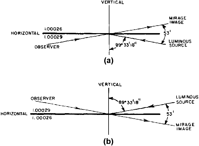
Par conséquent, lorsqu'une couche ou limite horizontale à travers laquelle n a la variation maximum supposée de 1,00029 à 1,00026 est illuminée par une source lumineuse (direction de propagation de dense à rare), l'angle d'incidence doit dépasser 89,5 ° (½ ° d'angle grazing) afin d'obtenir une réflexion totale et une image de mirage possible. For all practical purposes, 0.5 ° peut être considéré comme l'angle quasi-maximum d'illumination qui permettrait la formation d'un mirage. Lorsque l'indice réfractif diminue avec la hauteur à travers la limite et que l'illumination vient d'en-dessous, l'image du mirage apparait à une distance angulaire maximum d'environ 1 ° au-dessus de la véritable position de la source lumineuse comme illustré en figure 6a. Par conséquent, 1 ° d'arc doit représenter à peu près la distance angulaire maximum que l'on peut attendre entre la véritable position de la source lumineuse et son image réfractée. Lorsque l'image apparait au-dessus de la véritable position de la source, le mirage est qualifié de mirage supérieur. Lorsque l'indice réfractif augmente avec la hauteur et que l'illumination vient d'au-dessus, un mirage inférieur apparait, i.e., l'image se situe en-desous de la véritable position de la source comme montré en figure 6b. En termes de gradient vertical de température, le mirage supérieur est associé à une inversion et le mirage inférieur à une large temperature-lapse.
It is evident that the presence of a layer of large temperature gradient is necessary but not sufficient for mirage formation. A remaining requirement is the presence of light that illuminates the layer at grazing incidence. The incident light can originate from a physical source such as sun, moon, or planet, or it can be skylight or sunlight reflected from the ground.
Whether the mirage is observed or not depends on the position of the observer with respect to the light source and the refracting layer. The planar geometry involved in a mirage observation can be illustrated by applying Eq. (3) :

to a rectangular coordinate system in which the abscissa coincides with the ground. For simplicity it is assumed that
n2 = n02 - z
(i.e., the refractive index, n , decreases with height), so that the solution to Eq. (3) represents a family of parabolas of the form

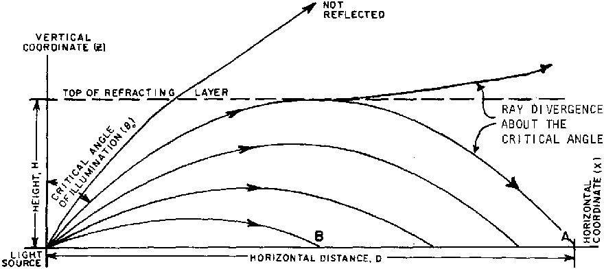
(In applying Eq. (3), z represents az' where z' has units of height and a is the scale factor). The family of parabolas, sketched in Fig. 7, can be thought of as representing the light rays from a point source located at the origin of the coordinate system. Using the upper and lower limit of the optical refractive index, no = 1.00029 and n = 1.00026, the largest horizontal distance (D) is covered by the light ray for which Thetao = 89.5° (angles are exaggerated in Fig. 7). All mirage images must be observed within this distance (see Fig. 7). D can be expressed in terms of the height (H) of the refracting layer as follows. For each member of the family of parabolas, z is maximum at the point where (dz/dx) = 0, i.e., at the point :
n0cos2 Θ0, x = n02sin2Θ0
Since each member is symmetric with respect to this point also,

(n2 = n2o, no = 1.00029, n = 1.00026, thetao = 89.5°)

Hence, D ~ 500H, i.e., all mirage images in this particular case are observed within a distance from the light source that is about 500 times the thickness of the refracting layer. For example, when the thickness of the refracting layer is 10 meters, no mirage observations of a particular object are likely beyond a distance of 5 km. At about 5 km an image of the object Mai appear at an elevation of about 0.5°, while within 5 km images Mai appear at increasingly lower elevation angles until the eye can no longer clearly separate the image from the source.
The preceding discussion applies only to the case where the observer is located within, or at the boundary of, the mirage-producing layer, If the observer is some distance above or below the mirage-producing layer, mirages of much more distant objects may appear.
From the above, it is evident that principal characteristics of the optical mirage are the small elevation angles under which the phenomenon is observed (≤1°) and the large distances (tens of kilometers) between observer and "mirrored" object that are possible. The geometry of the mirage explains why many observations are made on or near horizontally extensive, flat terrain such as deserts, lakes, and oceans and frequently involve images viewed through binoculars (oases, ships, islands, coastal geography). Furthermore, the above geometry illustrates that the duration of a mirage observation is critically dependent on whether or not the source and observer are in relative motion. For example, when the light source is moving in such a way that the angle of illumination, Thetao, oscillates around the critical angle, a stationary observer located at A in Fig. 7 Mai see a mirage image that alternately appears and disappears.
On the other hand, when the observer is moving relative to the source (from A to B in Fig. 7), the mirage image can change elevation, thereby creating an illusion of motion.